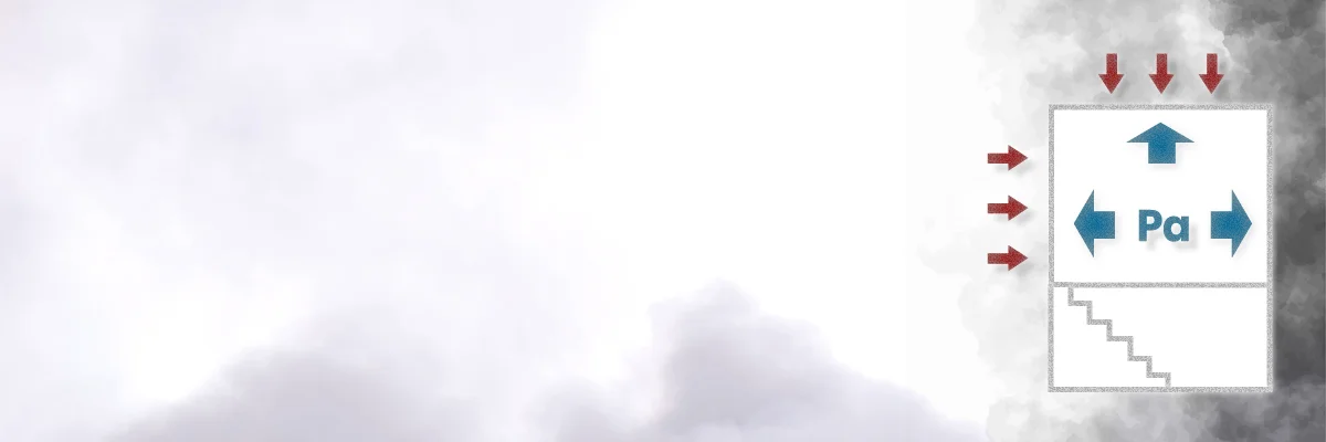
A pressurisation system is supposed to keep smoke out of a protected stair. It does that by pushing the stair to a higher pressure than the corridors and lobbies on each level. Smoke flows from high pressure to low pressure, so if the stair is the high-pressure zone, smoke can’t get in.
Simple enough on paper.
The problem is what happens when the doors close. Every closed door is a leakage path the fan has been working against. Close them all, and the fan keeps pushing air into a stair that has nowhere to send it. Pressure climbs. Once the pressure across a closed door gets high enough, no one can pull that door open. Not a firefighter in full kit. Not a resident escaping at 3am. Not the maintenance engineer doing the annual test.
That’s the failure mode overpressure relief exists to prevent.
What Overpressure Relief Actually Does
Overpressure relief is a vent, damper, or window that opens automatically when the pressure inside the stair rises above a set threshold. It bleeds the surplus air to outside, or to an adjacent unpressurised space, so the pressure differential across closed doors stays inside the design window. If you want a short definition of the term, see the Vent Trade glossary.
The system isn’t trying to drop pressure to zero. It’s trying to hold it in a band: high enough to stop smoke getting in, low enough that the doors still open.
On UK pressurisation systems designed to BS EN 12101-13:2022, the standard sets a 30 Pa minimum overpressure across the protected space. UK industry typically designs to 50 Pa across the closed door to give headroom against leakage and weather effects, with 60 Pa as the practical working ceiling derived from door geometry, and 100N of force at the handle as the hard cap on door operability. Whichever of the 60 Pa ceiling or the 100N door-force limit is reached first governs the relief sizing. A system running steady-state at 65 or 70 Pa breaches the 100N door-force limit and fails the standard.
The overpressure relief vent is the safety valve. It does nothing while doors are open and the fan is fighting leakage. As soon as the doors close and pressure starts to spike, the relief opens and lets the excess go.
The Physics: Door Force And Pressure Differential
The maths is the part most people skip. It’s worth understanding because it explains why the 50 Pa, 60 Pa and 100N numbers exist.
The full calculation in BS EN 12101-13:2022 accounts for door geometry and the lever ratio between the pressure-loaded face and the handle. A simplified version helps explain why the limits matter, but it has to be applied in two steps:
Step 1 (pressure force on the door face): F_face = P x A Step 2 (force at the handle): F_handle = (F_face x k) + C
Where P is the pressure differential across the door (Pa), A is the door area (m²), k is the lever ratio between the centre of pressure and the handle (typically around 0.54 for standard UK door geometry), and C is the force needed to overcome the closer itself (typically 25 to 30N for a CE-marked self-closer). The real handle force depends on hinge geometry, because the door handle isn’t at the centre of pressure, so the moment about the hinge governs.
For a standard stair door at 2.1m x 0.9m, the area is 1.89m². Indicative numbers:
- At 50 Pa, the pressure component on the door face is 50 x 1.89 = 94.5N. Resolved to the handle through the lever ratio (handle around 70mm from the leading edge, lever factor about 0.54), the handle sees roughly 51N from pressure. Add a 25 to 30N closer and you’re at 76 to 81N at the handle. Inside the limit.
- At 60 Pa, the pressure force on the door face is 113.4N. Resolved to the handle, that drops to around 61N from pressure, plus a 25 to 30N closer, giving roughly 86 to 91N at the handle. Right up against the limit.
- At 80 Pa, the pressure force on the door face is 151.2N. Resolved to the handle through the lever ratio, that drops to around 82N from pressure, plus a 25 to 30N closer, giving roughly 110N at the handle. Over the 100N limit. That’s the point where a firefighter wearing 25kg of kit and an SCBA mask, breathing hard, struggles to pull the door open consistently.
The 100N ceiling in BS EN 12101-13:2022 isn’t an arbitrary number. It’s the force a person under stress can apply consistently with one hand, on a door handle, while carrying something or holding a child. Go above it and the stair stops being usable. Pair it with the 60 Pa maximum overpressure and you have the two boundary conditions that drive every relief sizing calculation.
That’s why the relief vent matters. Without it, every closed-door condition is a runaway pressure event.
Where Overpressure Relief Sits In The System
In a typical UK Class 1 or Class 2 pressurisation system, you’ll find the overpressure relief vent at the head of the stair, either:
- Discharging directly to outside through the roof or a wall opening
- Bleeding into an adjacent unpressurised space (a lobby, accommodation, or transfer duct)
The vent itself can take three forms, and the choice matters more than people realise.
Motorised Damper
A powered damper driven by an actuator that responds to a pressure sensor in the stair. When the differential climbs above the setpoint (usually 50 Pa), the controller opens the damper. When it drops back, the damper closes.
Strengths: Precise control. Auditable. Failsafe positions can be programmed. Integrates with O Range Connect software for monitoring.
Weaknesses: Needs a power supply, a sensor, a controller, and commissioning. More to go wrong. More to maintain.
Motorised dampers are the right choice on large or complex systems where the pressure setpoint needs active control and you want telemetry on the smoke control panel.
Gravity Damper
A counterweighted flap that opens when air pressure on one side exceeds the weight holding it shut. No power, no sensor, no controller. The damper is calibrated to lift at the design pressure and reseal when pressure drops.
Strengths: Cheap, mechanical, no power needed. Almost no maintenance.
Weaknesses: Less precise. Calibration drifts over time. Birds and weather can foul the seal. No feedback to the control panel.
Gravity dampers are common on smaller residential stair pressurisation systems where the pressure profile is predictable and budget is tight.
Barometric Damper
A spring-loaded damper that opens against a calibrated spring force. Similar to gravity in concept but with mechanical force replacing weight. Used where gravity damper geometry doesn’t work (vertical orientation, restricted ceiling space, side-wall discharge).
Strengths: Works in any orientation. Settable across a range. No power.
Weaknesses: Springs lose tension. Annual recalibration matters more than people think.
What The Standards Actually Require
Two standards apply to UK pressurisation systems and you need to read both. BS EN 12101-6:2022 covers the kits and components: the fan, the dampers, the controller. BS EN 12101-13:2022 covers the design, calculation methods, installation, acceptance testing, routine testing and maintenance. The old single BS EN 12101-6:2005 was split into these two documents during autumn 2022 (Part 6 in September, Part 13 in October). Anyone designing or commissioning a system today should be reading the current published version of both, not relying on the withdrawn 2005 edition or on cited section numbers from a blog post.
The 2022 revision also retired the old Class A to Class F system. BS EN 12101-13:2022 uses two classes only:
- Class 1. Pressurisation for means of escape. Minimum 1 m/s air velocity through an open door on the fire floor.
- Class 2. Pressurisation for firefighting. Minimum 2 m/s air velocity through an open door on the fire floor.
Underpressure-only systems have been removed from the standard.
The headline requirements that drive overpressure relief design are these:
Pressure differentials. The standard sets a 30 Pa minimum overpressure across the protected space. UK practice rarely designs below 50 Pa because the smoke barrier becomes less resilient against weather effects and door swings as differential drops, and 60 Pa is the practical working ceiling. Above 60 Pa, door-opening force typically breaches 100N and the system fails the standard.
Door-opening force. Maximum 100N applied at the door handle with the system running and all other doors closed. This sits alongside the 60 Pa pressure ceiling, not in place of it. Both constraints apply. Relief sizing has to keep the system inside both.
Air release. Where the pressurisation system would otherwise drive the door-opening force above the 100N limit or push pressure above 60 Pa under closed-door conditions, an air-release path must be provided. This is the requirement that drives overpressure relief.
Commissioning. The commissioning test includes a door-force measurement at every floor with the system running, plus pressure measurement. The installer measures actual force at the handle and actual differential. If either exceeds the limits, the system fails and the relief vent gets resized, recalibrated, or repositioned.
What the standards don’t do is hand you the maths. That’s left to the designer. Which is one of the reasons we see badly-relieved systems on commissioning more often than we should. Read more on what good commissioning practice looks like.
How Sizing Works In Practice
You can’t pick a relief vent off a shelf. It has to be sized for the fan, the leakage characteristics of the stair, the geometry, and the design pressure.
The starting point is the fan’s pressurisation airflow at the design pressure, usually quoted in m³/s. Subtract the leakage rate through closed doors and other gaps at the design pressure. Whatever is left over has to go through the relief vent.
A worked example. Take a 10-storey residential stair, single fan, design airflow 4.5 m³/s at 50 Pa. Measured door leakage at 50 Pa across 10 doors works out at around 1.8 m³/s. The relief has to handle 4.5 minus 1.8 = 2.7 m³/s when all doors are closed.
These numbers are illustrative, not benchmarks. Real airflow and leakage figures depend on door specification, building envelope, and measured leakage during commissioning.
For a motorised damper at 50 Pa differential, that’s roughly 0.45 to 0.9m² of free area depending on the overall system loss coefficient including duct, weatherhood and screen losses. A bare damper sized off Q = Cd x A x sqrt(2 x dP / rho) with Cd around 0.6 to 0.65 lands at the smaller end. Add a long discharge duct, a weather louvre and a bird screen and you can easily double the required area. For a gravity damper, the geometry forces you larger again because the damper has to be light enough to open at the right pressure and that limits its area-per-unit-weight.
This is where the designer earns their fee. Get the sizing wrong and one of two things happens: the relief opens too early (pressure drops below 50 Pa and smoke gets in) or it opens too late (pressure breaches 60 Pa, door force exceeds 100N, and the user can’t open the door).
The Most Common Failures We See
Relief vent not connected to outside. A gravity damper bleeding into a service shaft that’s already partially pressurised. The damper opens but the pressure has nowhere to go. The stair pressure climbs anyway. The door force exceeds 100N. The system fails the test and no one knows why until someone traces the duct route.
Relief vent sized for the wrong fan. The original design was for a 3.5 m³/s fan. Someone uprated the fan to 5 m³/s during construction (because the leakage tests were worse than predicted) and left the relief vent as drawn. The relief can no longer handle the surplus. Door force spikes on every door-closed event.
Gravity damper calibration drifted. Counterweight slipped, hinge fouled, dust accumulated on the seal. The damper now opens at 75 Pa instead of 50 Pa. Door force at the upper floors is unmanageable. Found during a maintenance inspection two years after commissioning. Should have been caught annually.
Pressure sensor placed in a draughty position. The sensor reads ambient gust pressure on the leeward face of the building and tells the controller the stair pressure is higher than it really is. The motorised relief opens needlessly, smoke barrier breaks down on the fire floor.
Relief acoustically tied to escape route. Relief discharging into a corridor with no acoustic treatment. Fan noise transmits through the open damper, residents complain, building manager locks the damper shut. System fails next test catastrophically.
Most of these are commissioning or maintenance failures, not design failures. Which is why the annual test on a Class 1 or Class 2 pressurisation system has to include a measured door-force check and pressure check at every floor, not just a “fan runs, panel green” walkthrough.
When You Definitely Need It
If you’re specifying or installing any of the following, you need overpressure relief as part of the package:
- A Class 1 pressurisation system (means of escape) to BS EN 12101-13:2022
- A Class 2 pressurisation system (firefighting) to BS EN 12101-13:2022
- Any single-fan system without variable speed drive control on the supply fan
- Any system retrofitted into an existing building where you can’t accurately predict leakage characteristics
There’s a separate point worth flagging. In higher-risk buildings (the Building Safety Act 2022 section 65 threshold sits at 18m or 7 storeys with at least two residential units), the design and verification of pressurisation systems attracts additional scrutiny from the Building Safety Regulator. That’s a separate regulatory framework, not a BS EN 12101-13 class. The HRB regime drives evidence and accountability requirements; the system class drives the engineering design. They overlap in practice but they aren’t the same thing.
BS 9991:2024 then sits over the top for residential buildings and adds height thresholds you have to design around. Above 30 metres top storey, natural smoke shafts are no longer permitted for stair lobbies, so you’re into mechanical extraction or pressurisation. Above 60 metres, mechanical smoke extraction has to be designed to the pressure differential principles in Annex D of BS EN 12101-13:2022. Read the BS 9991:2024 guide alongside this.
Where you might not need a discrete relief vent: some designs use VSD-controlled supply fans that throttle back when differential rises. Even there, most designers fit a relief as a failsafe because the drive response isn’t instantaneous and a sticky door closer can spike pressure faster than the drive can react.
How This Interacts With Other Systems
Pressurisation systems and natural smoke vents don’t always coexist happily. A residential building with AOV windows on the corridors and a pressurised stair has two systems pushing different pressure profiles. The corridor AOV is depressurising the lobby. The stair pressurisation is pressurising the stair. The door between them sees the sum of both.
If the AOV opens to vent corridor smoke and pulls the lobby down to negative pressure relative to outside, the door between lobby and stair now has 50 Pa from the stair side plus whatever the AOV is generating. The door force climbs and the 60 Pa pressure cap gets breached faster than the single-system calculation predicts.
The overpressure relief has to be designed knowing what the corridor smoke control is doing. This is where system integration matters: the controls have to talk to each other, the cause-and-effect has to account for the combined pressure profile, and the relief has to be sized for the worst case.
The same applies to smoke and natural dampers on lift shafts. A pressurised lift shaft adds another pressure source to the building. A relief vent designed for the stair alone won’t cope if the lift shaft is dumping pressure into adjacent spaces during a fire.
What This Means For Specifiers
Three things.
First, if your design includes pressurisation, the door-force calculation and the 60 Pa pressure ceiling are the two controlling numbers. Not the design airflow. Not the fan static. Not the duct sizing. The numbers that determine whether the system is compliant are the force a firefighter or escapee has to apply at the door handle and the steady-state pressure across the closed door. Everything else exists to serve those numbers.
Second, the relief vent is part of the design, not an afterthought. It needs sizing, specifying, positioning, and commissioning the same way the fan and the controls do. Don’t let it get value-engineered out by a sub-contractor who’s never read BS EN 12101-13:2022.
Third, the maintenance regime has to include the relief. Annual door-force test at every floor. Pressure check. Damper inspection. Calibration check. Sensor verification. If the relief drifts and no one tests it, the next person to find out is the fire service.